power flame burner wiring diagram
Figure 4 C Lr Internal Wiring Diagram End Vent Burner Manualzz. We manufacture a wide range of commercial burners industrial burners boiler burners.
Power Flame Commercial Industrial Burners Ati Of Ny
Loose connections or faulty wiring.

. The two power leads black and white are located inside the burner panel. 61 Refer to wiring diagram shipped with burner and typical wiring diagrams Figures 5 and 5A. Charger hp diagram hstnn ca15 circuit.
Special panels for wall mounting or free standing applications are available at extra cost. 6 WIRING 61 Refer to wiring diagram shipped with burner. As a result they require less combustion volume for complete combustion and can be.
Flame safeguard control safety switch tripped out. Burner Controls Flame Scanners Spark Igniters and Gas Pilots. Each Power Flame VECTOR burner is factory test fired to ensure that components and systems are functional.
Reset and determine cause for apparent flame failure. On gm hei. FD FDM Installation Operation Manual - POWER FLAME INCORPORATED 6 2.
61 Refer to wiring diagram shipped with burner and typical wiring diagrams Figures 5 and 5A. Because each field application is unique the final burner set-up. X4 X4M Installation and Operation Manual - POWER FLAME INCORPORATED 1 1.
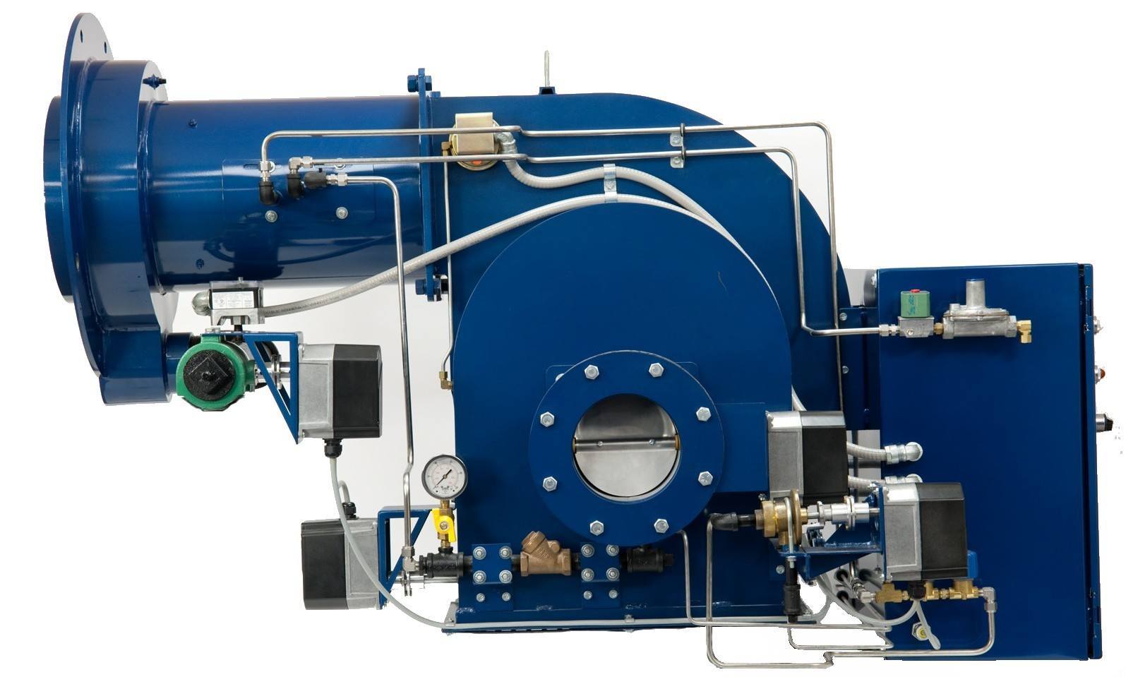
Power Flame Type C Burners are designed to produce greater flame turbulence and reduce flame size. Comprehensive wiring diagrams are furnished with each burner. Power Flame Type C Burners are designed to produce greater flame turbulence and reduce flame size.
Burner Director Management Boiler Burners Power Flame. Click here for the Power Flame library. 14 Pics about Diagram together with GM HEI Ignition Module Wiring Diagram.
Cmax Manual Rev 0217 A. 62Electrical installation must be made in accordance with the NEC NFPA 70 or Canadian Electrical Code Part 1 and applicable. Tighten all terminal screws and consult.
INSTALLATION 21 Burner Mounting. Food Beverage Oil Gas Petrochemical Metal Minerals Waste Management Power Generation Commercial Pulp. Diagram together with GM HEI Ignition Module Wiring Diagram.
General 211 Before beginning installation carefully study these. The fuel oil pump is remote on all. The two power leads black and white are located inside the burner panel.
The Power Flame Model CGO dual fuel burner presents an optimum state-of-the-art design for maximum combustion efficiency and operating dependability These packaged combustion. GENERAL INFORMATION 11 The X4 burner is a new generation of gas power burners designed to fire. As a result they require less combustion volume for complete combustion and can be.

Power Flame Type C Burner Combustion System

Vapor Power Steam Generators For Sale Smith Hughes

Acv Bmv5 Flame Burner Instruction Manual Manuals

I Have A Burnham Boiler With A Power Flame C2 G Burner And It Will Not Start The Burner Until The Fluid Temperature

Powerflame J Burner Manualzz

1960 Arcoflame American Standard Oil Burner Acd Model 602 Commercial Standard Cs195 60 Heating Help The Wall
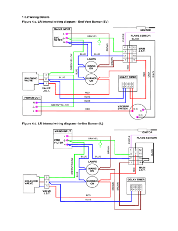
Figure 4 C Lr Internal Wiring Diagram End Vent Burner Manualzz
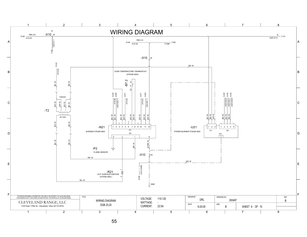
Pg 6 Wiring Diagram Cleveland Range Llc Cleveland Range Convotherm Combination Oven Steamer Gas 20 20 User Manual Page 62 81 Original Mode
![]()
Fireye Flame Safeguard And Combustion Controls

Wiring Diagrams Royal Series Royal Range Of California

Power Flame Type C Burner In Fire Test Youtube
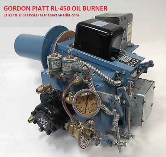
Oil Burner Manuals Download Free Oil Burner Manuals All Brands

Fuel Cells Could Power Future Apple Devices Complex
Powerflame Boilerdata Com

Gas Burner Primary Control Heater Service Troubleshooting

Articles

Panasonic Txnpf10q59 Sch Service Manual Download Schematics Eeprom Repair Info For Electronics Experts